cpacs Element |
CPACS root element
Namespace: Empty
Schema: Empty

 All
All
- Version
V3.4
- Date
2021-04-20
1. Overview
The Common Parametric Aircraft Configuration Scheme (CPACS) is an XML-based data format for describing aircraft configurations and their corresponding data.
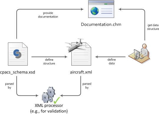
This XML-Schema document (XSD) serves two purposes: (1) it defines the CPACS data structure used in the XML file (e.g., aircraft.xml) and (2) it provides the corresponding documentation (see picture below). An XML processor (e.g., TiXI or XML tools in Eclipse) parses the XSD and XML files and validates whether the data set defined by the user (or tool) conforms to the given structure defined by the schema.
This documentation explains the elements defined in CPACS and its corresponding data types. Data types can either be simple types (string, double, boolean, etc.) or complex types (definition of attributes and sub-elements to build a hierarchical structure). In addition, the sequence of the elements and their occurrence is documented.
To link the XML file to the XSD file, the header of the XML file should specify the path of the schema file. An example could look like this:
<cpacs xmlns:xsi="http://www.w3.org/2001/XMLSchema-instance"
       xsi:noNamespaceSchemaLocation="pathToSchemaFile/cpacs_schema.xsd">
CPACS is an open source project published by the German Aerospace Center (DLR e.V.). For further information please visit www.cpacs.de.
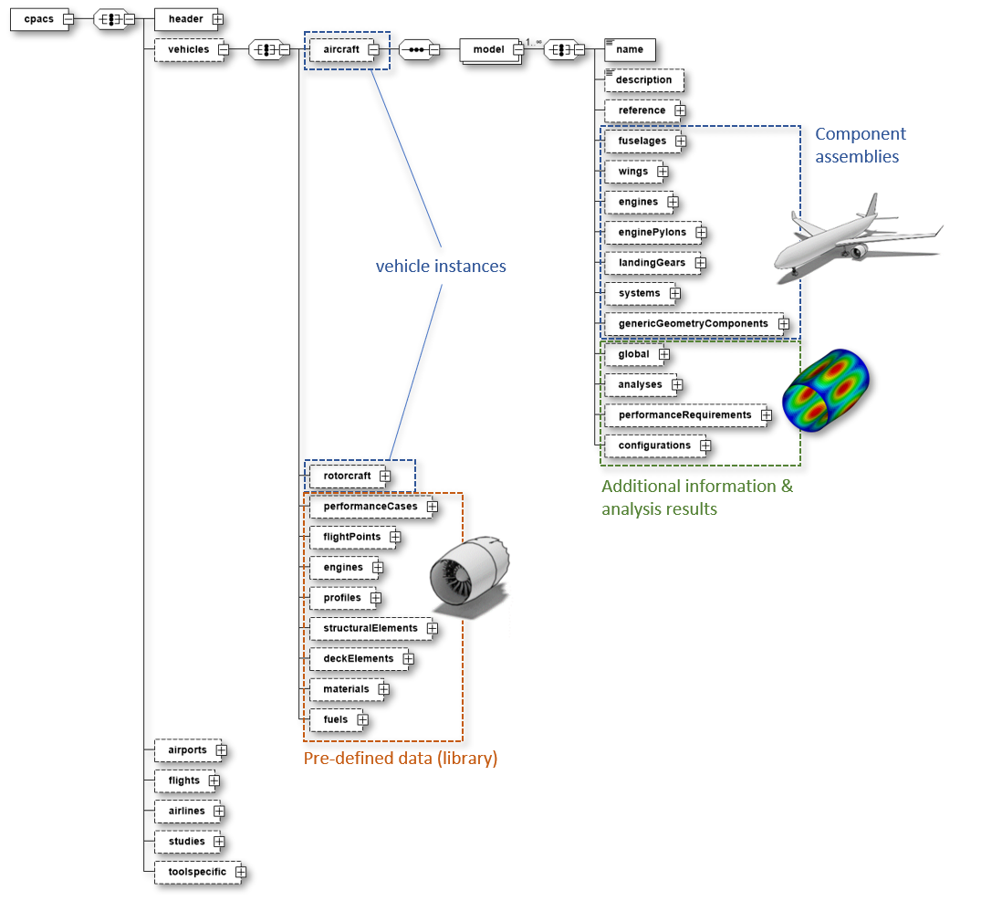
2. Data structure
CPACS data is modeled in a hierarchical structure whose underlying concept follows a top-down description of a system-of-systems which decomposes a generic concept (e.g., an aircraft or rotorcraft) into a more detailed description of its components. This originates from the conceptual and preliminary design of aircraft, where the level of detail is initially low and continues to increase as the design process progresses.
For some concepts within CPACS, however, a bottom-up approach is applied where the components are first defined in detail (sometimes referred to as library) and then linked within an instantiated higher-level concept. This is advantageous when used multiple times within complex systems, such as engines, which only have to be defined once in order to be referenced several times on the aircraft. The combination of these two methodologies is known as middle-out approach and enables the goal to fully parametrize aeronautical systems.
3. Coordinate Systems
3.1. CPACS coordinate system
Coordinate systems are a regular cause for ambiguous interpretation of data. In CPACS, the reference coordinate system is the CPACS-coordinate system. This coordinate system is used for most of the data. A single exception is made in order to keep aerodynamic data in an aerodynamic coordinate system. The following paragraphs outline the determination to known coordinate systems.
The CPACS coordinate system is the coordinate system identified by TiGL, CPACS's geometric library. It is a right-handed coordinate system. If an aircraft is defined in the CPACS coordinate system it will usually follow the directions listed in the table below.
Therefore, the CPACS coordinate system can be confused with the body-fixed coordinate system. While often the CPACS coordinate system and the body-fixed coordinate system overlap, this must not always be true. Several definitions for body-fixed coordinate systems exist (x-axis through nose and tail, x-axis perpendicular to nose plane). For non-symmetric aircraft, body-fixed coordinate systems become even more complicated. Hence, analysis tools should stick to the CPACS-Coordinate system. It remains to the designer to model the geometry accordingly.
The CPACS coordinate system does not rotate with flow. Hence, aerodynamic calculations do rotate their flow relative to the CPACS-coordinate system. If not stated explicitly different, e.g. for target lift-coefficients, results are returned in the CPACS coordinate system, i.e. the cfx-coefficient is parallel to the CPACS x-Coordinate, regardless of the way the geometry is defined.
The following table gives a "best-practice" advice on how to locate a geometry within CPACS. Different approaches are, of course, valid as well.
| Axis | Direction | Description |
| x | tailwards | from nose to tail |
| y | spanwise | from symmetry plane to the right wingtip |
| z | upwards | from landing gear to tip of vertical tailplane |
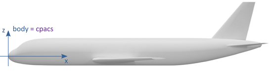
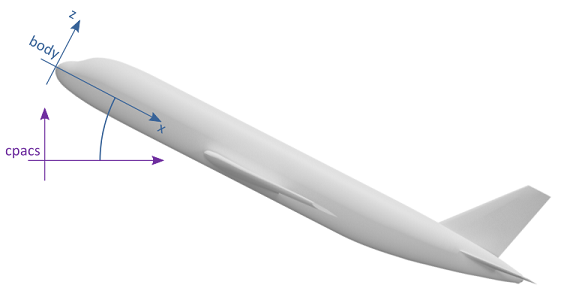
The following figures show an example of a geometry that is aligned with the CPACS coordinate system, i.e. the body-fixed coordinate system corresponds to the CPACS coordinate system.
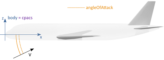
The aerodynamic analysis is relative to the CPACS coordinate system. That is, the angle of attack is represented by the dashed orange line. Results of the aerodynamic calculation are given in the CPACS coordinate system.
The following figures give an example of a geometry that is not defined in alignment with the CPACS coordinate system. It is a valid CPACS file, but only used in this example for demonstrative purposes.
The body axes and the CPACS coordinate system do not align. That is, the origin of the geometry is not at CPACS (0,0,0) but at a point in positive x- and z-direction.
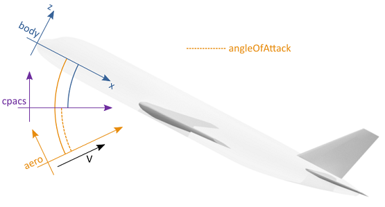
Again, the aerodynamic analysis is relative to the CPACS coordinate system. That is, the angle of attack is represented by the dashed orange line. Results of the aerodynamic calculation are given in the CPACS coordinate system.
3.2. Local coordinate systems via parentUID and transformation
Some elements in CPACS, in particular the geometric components, are described in local coordinates. The hierarchical data structure allows to define a local coordinate system either with respect to the coordinate system of the parent element or with respect to the global CPACS coordinate system. This is achieved by combining the two elements parentUID and transformation:
parentUID: An individual data hierarchy can be set up using the optional parentUID element. Here it is important that exactly one element does not contain the parentUID in order to identify the top element of this user-specific hierarchy. As soon as the parentUID (which refers to the uID of the parent element) is set, a local coordinate system of the corresponding node is instantiated.
transformation: This allows the coordinate system to be transformed via translation, rotation and scaling. As soon as the parentUID is set, this transformation refers to the local coordinate system (in the current CPACS version this only affects translation). An attribute refType is used to either make this explicit (refType="absLocal") or to override this and reference the global CPACS coordinate system instead (refType="absGlobal").
The following table summarizes the possible combinations of parentUID and transformation and the resulting coordinate system (local or global):
| parentUID not set | parentUID set | |
| transformation without refType | global | local |
| transformation with refType="absLocal" | global | local |
| transformation with refType="absGlobal" | global | global |
Note: The combination of transformation with refType="absLocal" and no parentUID is global, because the local coordinate system to which the transformation is referring to via refType equals the global coordinate system (see fuselage in the following example).
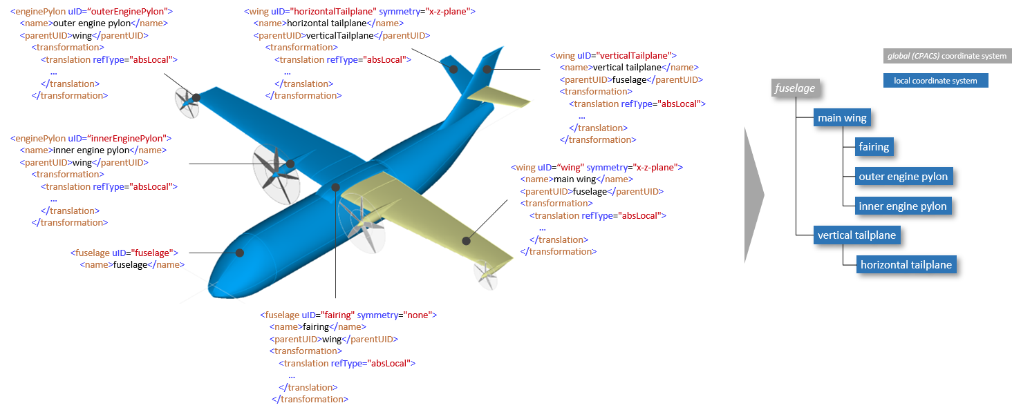
An exemplary use case further illustrates the concept of the coordinate system hierarchy. The CPACS schema shall not specify in advance that a wing is always be part of the fuselage and engines must always be part of the wing. In other cases the engine could be attached to the fuselage, which would not be possible via a predefined XML tree. The following figure shows how components of the aircraft are related to each other via the parentUID. The fairing is a child of the wing and is therefore automatically translated when the wing is translated. Likewise, the horizontal tailplane is a part of the vertical tailplane and is therefore affected by translation of the latter:
4. Units
There are no explicit attributes describing units in CPACS. The general convention is that all values must be given in the following SI-units:
| [m] | Position, Distance |
| [m2] | Area |
| [m3] | Volume |
| [kg] | Mass |
| [s] | Time |
| [K] | Temperature |
or in derived units, e.g.:
| [N] | Force |
| [Nm] | Moment |
| [W] | Power |
| [J] | Energy |
The only non SI unit used throughout CPACS is the angle in degrees [°]. For the sake of an intuitive use the angles are given in degrees rather than in radian [rad].
| [°] | Angle |
5. Splitting up a CPACS dataset into several files
To provide a better overview, it is possible to split up a CPACS dataset into several files. This can be done by inserting an <externaldata> node at an arbitrary position into the datatset. This node contains a <path> node with a URI to the external file(s), followed by one or more <filename> nodes, containing each a name of a file to be included at that position. Below, an example of such external data is given:
<?xml version="1.0" encoding="utf-8"?>
<cpacs xmlns:xsi="http://www.w3.org/2001/XMLSchema-instance"
       xsi:noNamespaceSchemaLocation="pathToSchemaFile/cpacs_schema.xsd">
    <vehicles>
        <profiles>
            <wingAirfoils>
                <externaldata>
                    <path>file:://airfoils</path>
                    <filename>NACA0010.xml</filename>
                    <filename>NACA2412.xml</filename>
                </externaldata>
                <airfoil uID="NACA0012">
                    <name>NACA 0012 Airfoil</name>
                    <pointList>...</pointList>
                </airfoil>
            </wingAirfoils>
        </profiles>
    </vehicles>
<cpacs>
Such an external file would look like:
<?xml version="1.0" encoding="utf-8"?>
<airfoil uID="NACA0010">
    <name>NACA 0010 Airfoil</name>
    <pointList>...</pointList>
</airfoil>
The file would be included completely, except for its title line <?xml version="1.0" encoding="utf-8"?> . This concept can also be used recursively (external files of external files), but it is important to prevent circle connections (file "A" loading file "B" loading file "C" loading again file "A" ...).
For path URI addresses, the trailing file separator "/" may be omitted. Below, some examples for path URIs are given:
- Absolute local path: file:///tmp or file:///c:/windows/tmp
- Relative local direcotry: file://relativeDirectory or file://../anotherRelativeDirectory
- Remote net ressource: http://www.someurl.de
With the help of the TiXI XML Interface TiXI, a CPACS dataset that is split into multiple files can be reassembled into a single tree structure for subsequent validation against the CPACS schema. The following commands are used to link external data sets:
- <externalFileName>: Name of the external data file
- <externalDataDirectory>: Directory of the external data file. Its content is analogous to the externaldata's path-element described above.
- <externalDataNodePath>: XPath of the node which is replaced with the content of the external file. In case that it is an external file of an external file, then it is the XPath in the outer external file. If, e.g., in the example above the pointList element would have also been loaded from an external file, then the entry would just be: externalDataNodePath="/airfoil". This is used primarily for loop-detection.
The merged data tree for the example above would look like:
<?xml version="1.0" encoding="utf-8"?>
<cpacs xmlns:xsi="http://www.w3.org/2001/XMLSchema-instance"
       xsi:noNamespaceSchemaLocation="pathToSchemaFile/cpacs_schema.xsd">
    <vehicles>
        <profiles>
            <wingAirfoils>
                <airfoil uID="NACA0010" externalFileName="NACA0010.xml" externalDataDirectory="file://airfoils" externalDataNodePath="/cpacs/vehicles/profiles/wingAirfoils">
                    <name>NACA 0010 Airfoil</name>
                    <pointList>...</pointList>
                </airfoil>
                ...
                <airfoil uID="NACA0012">
                    <name>NACA 0012 Airfoil</name>
                    <pointList>...</pointList>
                </airfoil>
            </wingAirfoils>
        </profiles>
    </vehicles>
<cpacs>
6. UIDs and references
The CPACS-dataset often uses references between nodes. Typically, these references define connections between elements which are located somewhere else in the hierarchical dataset (e.g. a wing is connected to a fuselage; a specific engine is connected to a pylon; etc.). These connections are defined by unique identifiers (uID) which are specified as attributes. Thus, there are elements which can be referenced via a uID attribute, e.g. a fuselage:
<fuselage uID="ATTAS_fuselage">...
as well as elements which refer to the former, e.g. a wing pointing to its geometrical parent:
<wing uID="e382bf5j">
    <name>ATTAS main wing</name>
    <parentUID isLink="True">ATTAS_fuselage</parentUID>
    ...
In previous CPACS versions, referencing elements were identified via the isLink="True" attribute. Since this is superfluous due to the explicit definition of the element properties via the CPACS schema, this attribute no longer needs to be listed. It is nevertheless a valid optional attribute to ensure compatibility with older datasets, but might be removed in future versions.
Since uIDs are only used to link nodes within the XML file, no naming convention is required. The characters only have to conform to the conventions of the xsd:ID type standardized by the W3C. UIDs, however, must be unique! Although a common practice for naming uIDs is their position in the data hierarchy (e.g. uID="mainWingSection3"), uIDs as shown in the above example are absolutely valid as well. It is therefore recommended to use the name element to convey human-readable meanings.
7. Usage of name, description and uID
CPACS is designed to serve as a central data exchange format in fully automated process chains. A key requirement is therefore that tools can automatically read and process an incoming CPACS file. A second requirement is that users can interpret the data set. To address both requirements, the following usage of the name and description elements in combination with the uID attribute is proposed:
name: A specification of the name element is usually mandatory for sequences of elements (e.g., if max occurence is unbounded [1..*]). Typical examples are wings/wing, aeroPerformance/aeroMap or missions/mission. Such elements must be able to be listed by tools, especially for visualization and reporting purposes, where the name element serves as a concise and human-readable indicator of the actual meaning of the corresponding element in the list (e.g., which wing, which aeroMap, which mission). This is usually a single word or a small number of words.
description: This element is usually optional and is used to add comprehensive and human-readable explanations. This is usually at least one explanatory sentence.
uID: As described in more detail in Section 6, the uID attribute is mainly used for internal referencing of CPACS elements. Further processing software, e.g. TiXI and TiGL, also use the uIDs to improve the robustness of the data query. Consequently, the uID attribute serves as a machine-readable indicator and does not claim to be interpretable by human users. In some practical use cases, the same string is chosen for uID and name. However, restrictions on the choice of characters for the uID attribute must be considered, for example that no spaces may be used and the uID must be unique.
<wing uID="main_wing">
    <name>Main wing</name>
    <description>This is the main wing which was designed by my awesome wing sizing design tool. Your tool should not try to read and interpret what I'm writing here as typos are not recognized by XML processors.</description>
</wing>
8. Symmetry
8.1. Specification of symmetric elements
Sometimes it might be useful to specify a part of the aircraft as symmetric instead of holding all the data twice in nearly identical form in the dataset (e.g. left and right wing are usually identical, except for the sign of the y-coordinate). Hence, some parts offer the option to set a symmetry attribute:
<wing symmetry="x-z-plane">
There are six possible attribute values:
- x-y-plane: Symmetry w.r.t. the x-y plane of the CPACS coordinate system
- x-z-plane: Symmetry w.r.t. the x-z plane of the CPACS coordinate system
- y-z-plane: Symmetry w.r.t. the y-z plane of the CPACS coordinate system
- inherit: Symmetry inherited from parent element (default behavior, i.e. also applies if attribute not set)
- none: Symmetry inheritance from parent element disabled
One example of how to apply the symmetry attribute is shown in Sec. 3.2. Another simplified example shown below illustrates the combination of different symmetry properties of 4 wings:
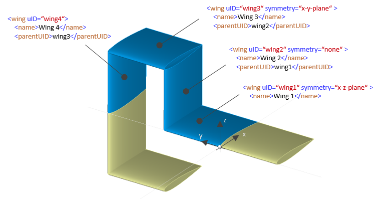
- Wing 1 is mirrored on the x-z plane.
- Wing 2 has wing 1 as parent element, but suppresses its symmetry inheritance.
- Wing 3 has wing 2 as parent element and sets a new symmetry at the x-y plane.
- Wing 4 has wing 3 as parent element and no symmetry attribute specified. Thus, it inherits the symmetry at the x-y plane from wing 3.
Note: The corresponding transformations are not shown here.
8.2. Referencing symmetric elements
All nodes (e.g., parentUID) in CPACS that refer to a component holding the symmetry attribute (e.g., wing) might also have a symmetry attribute to specify how symmetry is propagated through the resulting element hierarchy.
The symmetry attribute of a referencing element may take three values: symm, def, full:
- def: The element refers to the geometric component that has a symmetry attribute and refers only to the defined side of the geometric component.
- symm: The element refers to the geometric component that has a symmetry attribute and refers only to the symmetric side of the geometric component. (Similar to the previous _symm solution)
- full: The element refers to the geometric component that has a symmetry attribute and refers to the complete component. (This is the default behaviour)

For example, to refer to the "other" side of a mirrored wing the following the following syntax might be used:
<enginePylons>
    <enginePylon uID="pylon">
        <parentUID symmetry="symm">wing</parentUID>
Note: This feature is not implemented in TiGL. The upper figure is manually processed to illustrate the principle. In addition, there is an ongoing debate whether the approach is suitable for CPACS due to rapidly increasing complexity and unresolved implicit assumptions as to whether it is one or two components after mirroring. Therefore, it is advised to avoid using the symmetry attribute if possible.
9. Vectors and arrays
For large data sets (e.g. increments of aerodynamic coefficients due to control surface deflections) it is advantageous to map them via vectors and arrays instead of using a sequence of nodes for each data value. Therefore vectors and arrays are defined as semicolon-separated lists in CPACS. Via the documentation (derived from the XSD) of the corresponding nodes it has to be checked whether it is a vector or an array.
- Vector
The vector is meant as a one-dimensional-array. In such a node, the values are given in a semicolon separated list:
CPACS vector element<angleOfAttack>0.;1.5;3.;4.5;6;7.5;9.</angleOfAttack>
- Array
As for vectors, multi-dimensional arrays provide values in a semicolon separated list. An array is always preceded by a sequence of vectors, containing the dimensions and index values. Which vectors of an array are dimensioning is specified in the respective documentation of the array.
Usage of a CPACS array element<altitude>1000.;2000.;3000.</altitude> <!-- vector element --> <incrementMaps> <incrementMap uID="incMap_b3ac2"> <controlSurfaceUID>InnerWingFlap</controlSurfaceUID> <controlParameters>-1;-0.5;0;1</controlParameters> <!-- vector element --> <!-- array of dimension length(altitude) x length(controlParameters): --> <dcl>11.;12.;13.;14.;21.;22.;23.;24.;31.;32.;33.;34.</dcl>
Values for cl increments:Control parameter = -1 Control parameter = -0.5 Control parameter = 0 Control parameter = 1 Altitude = 1000m 11. 12. 13. 14. Altitude = 2000m 21. 22. 23. 24. Altitude = 3000m 31. 32. 33. 34.
10. Control Parameters
Control parameters are abstract parameters, linking a generic floating point value to a certain status of a control device (e.g. control surface, landing gear, suction system, brake parachute, ...). For control surfaces, such a data pair (control parameter and control surface deflection status) is called a <step> and the ordered list of all steps for a control surface forms its deflection <path>.
The control parameter values for each step are arbitrary floating point values. However, it is strongly recommended to use values between -1. and +1., or between 0. And +1. (depending on the type of control surface). The smallest and the largest value implicitly define the maximum deflection limits. It is mandatory, that the value “0.” is within the specified range, as this value is treated as undeflected and used to specify a “clean” aircraft configuration (e.g. used in the clean aero performance map). It is recommended, but not mandatory to specify a <step> with a <controlParameter> of 0. Consequently, no <controlParameter> must be used twice within a single <path> definition. Deflection values between two specified steps are handled by linear interpolation.
The following example shows the usage of control parameters within a control surface deflection path definition:
<controlSurfaces>
  <trailingEdgeDevices>
    <trailingEdgeDevice uID="InnerWingFlap">
      ...
      <path>
        ...
        <steps>
          <step>
            <controlParameter>-1</controlParameter>
            <hingeLineRotation>-20.</hingeLineRotation>
          </step>
          <step>
            <controlParameter>-0.5</controlParameter>
            <hingeLineRotation>-10.</hingeLineRotation>
          </step>
          <step>
            <controlParameter>0</controlParameter>
            <hingeLineRotation>0.</hingeLineRotation>
          </step>
          <step>
            <controlParameter>1</controlParameter>
            <hingeLineRotation>5.</hingeLineRotation>
          </step>
        </steps>
        ...
11. Atmosphere
At some places in CPACS, an atmosphere has to be selected (e.g. for connecting an altitude with a certain pressure or density). Currently, CPACS does only support a single atmospheric model: The ICAO Standard Atmosphere (ISA) from 1993 (see ICAO Doc 7488/3 'MANUAL OF THE ICAO STANDARD ATMOSPHERE', third edition, 1993) It covers temperature, pressure, density, speed of sound, dynamic viscosity and kinematic viscosity with respect to altitude. In CPACS, 'altitude' means what is called 'geopotential altitude' (H) in the ISA reference document and is given in [m]. For details, see ISA manual, section 2.3, page E-viii f. ISA covers a range from -5000 m to 80000 m.
Temperature offsets are introduced on top of the definitions in the ISA manual (which does not cover such variations). The offset model is based upon the idea that the pressure at a fixed geopotential altitude is independent from temperature offset (pressure altitude). The temperature offset changes only the density (following rho = p / Gas Constant / T) (and viscosity, of course)
CPACS 3.4
Release in April 2022
- Revision of decks definition (compatibility break)
- Mass breakdown: add mSparSkins and mSparCells to mSpar
- Mass breakdown: fix hierarchical error in mMiscellaneous (compatibility break)
- Mass breakdown: fix typo in mPylon (compatibility break)
- Nacelle guide curves: set description optional
- Mission definition: add uID to elements in geographicPointConstraintType
- Mission definition: add powerFraction, powerRemaining and powerConsumed to missionSegmentEndConditionType
- Mission definition: rename referenceEndCondition to referenceEndConditionUID in constraintSettingsType (compatibility break)
- Mission definition: rename reqClassification to requirementClassification in flightPerformanceRequirementType (compatibility break)
- Add contour coordinates for cell definition
- Add vehicle independent node for external geometry
- Remove paxFlow element from aircraftAnalysesType (compatibility break)
- Docs: improve documentation of name, description and uID usage
- Docs: add description of parentUID concept
- Docs: add description of symmetry inheritance
- Docs: add description of engine nacelles
- Docs: add description of mission definition
- General improvements of the documentation
CPACS 3.3
Release in June 2021
- Revision of the mission definition including parameter lapses within segments (compatibility break)
- Revision of the point performance definition (compatibility break)
- Revision of performance requirements (compatibility break)
- Revision of landing gears (compatibility break)
- Revision of control surface tracks definition (compatibility break)
- Load analysis: Revision of flightLoadCasesType (compatibility break)
- Load analysis: Revision of aeroCasesType (compatibility break)
- Load analysis: loadEnvelopesType relocated and envelope simplified to a single uID-Sequence (compatibility break)
- Load analysis: Replaced dynamicAircraftModel elements by loadApplicationPointSets (compatibility break)
- Flight dynamics: Group flightPerformance, flyingQualities and trim under flightDynamics parent node (compatibility break)
- Introduced a configuration node to describe aircraft and payload configurations
- Fuselage profiles: Introduced rectangle and super ellipse as standard profiles
- Fuselage profiles: Added vector to specify curve parameters for profiles with kinks
- Internal structure: Added standard profiles to profile based structural elements
- Internal structure: Added ribPosts element to wingRibCrossSectionType
- Internal structure: Upper and lowerCap now optional in sparCellType
- Internal structure: Stringers and frames can reference sections
- MassBreakdown: Set mass inertia Jxy, Jxz and Jyz optional
- MassBreakdown: Added mMiscellaneous element
- MassBreakdown: Added fuselage walls
- Added flight envelope to aircraft global element
- Added new base types: doubleVectorBaseType, posIntVectorBaseType, doubleArrayBaseType
- Added 'none' and 'inherit' to list of symmetry flags
- Set mapType attribute of vector and array elements to optional (requires TiXI>=3.1)
- AeroMaps: Defined angleOfSideslip as input and added distinction between minimum and maximum angleOfAttack in aeroLimitMaps (compatibility break)
- AeroMaps: Added missing singular incrementMap element to incrementMaps in aeroLimitsMap (compatibility break)
- AeroMaps: Adopted the camelCase style for damping derivatives (compatibility break)
- Introduced common nomenclature for speeds and altitudes (compatibility break)
- Control distributors are set to optional
- Added instructions for superposition of control surface deflections
- Further elaboration of development standards
- General improvements of the documentation
CPACS 3.2
Release in February 2020
- Replaced tool-specific elements with xsd:any element and strict schema request for validation
- UIDs adapted to type xsd:ID and xsd:IDREF
- UIDs optional for transformationType and pointTypes
- Replaced xsd:sequence elements with xsd:all elements where possible
- CpacsVersion element set to optional
- GuideCurves are now optional for nacelleCowlType
- Documentation adaptions
CPACS 3.1
Release in August 2019
- Redefinition of aeroPerformanceMaps
- Added nodes for detailed engine pylons and nacelles
- Added nodes to model generic walls
- Extension of material definition
- Added fuselage compartment definition
- Added fuselage fuel tank definition
- Explicit wing stringer definition integrated into wing stringer definition
- RelativeDeflections renamed to control parameters
- Control distributors modified to only have a single command input vector
- "cpacsVersion" restricted to current schema version
- Code cleanup
- Cpacs_schema.xml removed
- Documentation adaptions
CPACS 3.0
Release in Jul 2018
- New component segment definition; this is affecting all structural components of wings
- Renamed angleOfYaw into angleOfSideslip
- Fixes in documentation
- Made all uID attributes required
- Minor fixes in choices and typos
- Added nodes for the geometry of generic system components
- Added performance requirements for aircraft models
- Redefined the whole mission definition including point performances
- Made link to missionUID in trajectory optional
- Added new parameters to enginePerformanceMap
- Relocated mFixedLeadingEdge and mFixedTrailingEdge within the massBReakdown structure
- Changed aeroPerformanceMap to use altitude and standard atmosphere instead of reynolds number
- Added an optional local direction for guide curves and an illustration image
- Announced toolspecifics definitions as deprecated; will be removed from CPACS in next release and should be managed in separate namespace by tool maintainers
- Added an option for aerodynamic performance maps of elastic aircraft
- Enabled the definition of multiple aeroPerformanceMaps
- Enabled the use of spar points for rib placement and rib points for spar placement
- Added explicit stringer definitions for wing cells
- All issues for this release can be found online
- https://github.com/DLR-LY/CPACS/issues
CPACS 2.3.1
Release in Jul 2016
- CPACS 2.3.1 is a beta release, all parameters may be subject to change.
- Added a branch for the definition of design studies.
- Added thermal properties for materials.
- Revised the definition of flights/flightplans.
- Added an airline definition.
- Added structure for skid gear components.
- Changed the units for material density to SI units.
- Revised the top level fleets node and put it into the new airline node.
- All issues for this release can be found online
- https://github.com/DLR-LY/CPACS/issues
CPACS 2.3
Release in Nov 2015
CPACS 2.3 is the fourth public release of CPACS. Major changes include:
- Included vector notation for weight and balance.
- Included flight system and flight dynamic information.
- Included top level aircraft requirements.
- Included a prototype for detailed nacelle geometries.
- Included structural mounts.
- Extended aero data set for loads.
- Extended the mass breakdown.
- Updated the symmetry definition, please take a look at the documentation point 5 and 6.
- All issues for this release can be found online
- https://github.com/DLR-LY/CPACS/issues
CPACS 2.2.1
Release in Feb 2015
- CPACS 2.2.1 is a beta release, all parameters may be subject to change.
- Included preliminary definition of guidecurves.
- Included additional means to describe the wing structure.
- Included preliminary fuselage fuel tanks.
- Included preliminary load envelope.
- Included preliminary flight performance and flight qualities. (flight dynamics will follow)
- Updated toolspecifics
- Updated uncertainty definition
- all issues can be found online
- http://code.google.com/p/cpacs/issues/list
CPACS 2.2
Release in May 2014
- CPACS 2.2 is the third public release of CPACS. Major changes include
- Additions and changes to the loadCaseType.
- Included additional genericGeometricEntities for bellyfairings etc.
- The mass breakdown is extended for a more detailed fuselage strucuture.
- Steadiness information on the geometry is excluded from CPACS 2.2. CPACS 2.3 will include optional guidelines for smoother surfaces.
- Uncertainties can now be specified (CPACS 2.2alpha doubleBaseType, CPACS 2.2 also in vector notations)
- all issues can be found online
- http://code.google.com/p/cpacs/issues/list
CPACS 2.1
Release in May 2013
- CPACS 2.1 is the second public release of CPACS. Most of the implementation was already included in CPACS 2.01
- included fuselage structure and cabin definition
- all data is defined according to the CPACS coordinate system. That is the initial coordinate system in which geometries are defined. Therefore, it can but must not meet your body axis.
- the mass breakdown is extended for a more detailed wing strucuture
- profiles can now be included based on a two-dimensional class shape transformation. The old parametrization will still be available. TIGL will learn CST asap.
- all issues can be found online
- http://code.google.com/p/cpacs/issues/list
CPACS 2.01
Release in Nov 2012
- CPACS 2.01 is an internal release for the VAMP project. It is the testbed for CPACS 2.1
- included fuselage structure
- additions to the load case definition
- all issues can be found online
- http://code.google.com/p/cpacs/issues/list
CPACS 2.0
Release in Mar 2012
- CPACS 2.0 is the first public release
- large impacts on the documentation
- all issues can be found online
- http://code.google.com/p/cpacs/issues/list
- compatible with TIGL 2.0
- excluded fuselage structure, reintegration in CPACS 2.1
CPACS 1.6
Release in Jul 2011
- Thanks for the input on the documentation to Felix Dorbath, Till Pfeiffer, Alexander Koch, Falk Heinecke and Tom Otten
- preliminary added enginePylons
- deleted seatAssemblyPositionType
- updated toolspecific blocks from handbook aero and cpacs mass updater
- added weight and balance definition
- added loads reference axis and dynamic aircraft model
- added wing documentation
- added weights documentation
- added fleet documentation
- added paramam toolspecific documentation
- added wing tank definition
- changed some names in the massBreakdown
- deleted old loadCaseDefinitions
- no more plural element for loadAnalyses
- shifted groundforces to groundloadcases, this will need an update
- added noseLandingGear
- mainLandingGear can now have plural SideStruts
CPACS 1.5
Release in Feb 2011
- uID for transformation
- extended stringUIDBaseType with optional attribute isLink
- all elements xxxUID are now of Type stringUIDBaseType
- added new material definition from FA to distinguish between diffent material types
- changed fuselage structure definition due to input from BK
- changed rib definition in cells in component segments
- cleaned up material definition in component segments
- added cpacsVersion information to the header and updates types
- added area and length to the loadCase reference on wing strips
- added wingFuselageAttachment
CPACS 1.4
Release in Nov 2010
- Geometry definition for engine and nacelle added
- Trailing Edge Devices, Leading Edge Devices and Spoilers added
- Rotorcraft added, similar to aircraft
- Splitted up multiple Point Types
- sparCell added uID
- new inline Documentation introduced in CPACS type
CPACS 1.3
Release in Aug 2010
- Fuel definition added
- Introduced component segments for the wing structure
- Mission definition was updated
- VSAero toolspecific data updated
CPACS 1.2
Release in May 2010
- Fuselage Structure Elements are updated following the input from BK
- stringers>arbitrary additional parameters: yBezugAtStartX, zBezugAtStartX, yBezugAtEndX, zBezugAtEndX
- paxCrossBeams additional parameters: startX, endX
- cargoCrossBeams additional parameters: startX, endX
- paxCrossBeamStruts additional parameters: startX, endX
- cargoCrossBeamStruts additional parameters: startX, endX
- structure>pressureBulkhead: positionX instead of positionZ
- reinforcementNumberVertical: number of vertical reinforcements
- reinforcementNumberHorizontal: number of horizontal reinforcements
- maxFlectionDepth: max camber of pressure bulkhead
- reinforcementNumber: number of reinforcements rear pressure bulkhead
- sheetProperties: definition of sheet properties
- innerRadius: inner radius of the pressure bulkhead
- Dummy Wingbox element is included. This definition needs further enhancements
- cpacs>vehicles>aircraft>model>fuselage>fuselage>structure
- Wingbox:
- xStart: start of the wingbox area
- xEnd: end of the wingbox area
- zStart: upper limit of the wingbox area
- Damping Derivaties are added in the form of dcfxdp, dcfxdq, dcfxdr, dcfydp, etc. The data will be stored in the model/global/aeroperformaneMap under a new dampingDerivatives element. Unit is deg/sec.
- StructureProfiles are defined in the profiles element. They are referenced in structuralElements for several entities such as stringer, frame etc. Currently they are referenced via 'structuralProfileUID' for name consistency it should be either only 'structure' or only 'structural'
- Control Commmands. The chain between pilot inputs and controlsurface deflections is now closed.
- Parameters located at cpacs\vehicles\aircraft\model\systems
- cockpitControl: links from pilotInput to commandCase
- commandCase: links from commandCase to controlDistributor or controlFunction
- controlDistributor links to the controlSurface
- controlLaws includes controlModes automatic and manual
- controlModes contain controlFunctions
- TraFuMo toolspecific data added
CPACS 1.1
Release in Feb 2010
- Fleets model added. The fleets modeling from CATS is introduced to CPACS 1.1
- Reference changed. The reference type in wingSegmentStripCoefficientsType was changed from referenceType to pointType