loadApplicationPointSetType Complex Type |
Load application point set
Namespace: Empty
Schema: Empty

| Name | Occurrences | Description |
|---|---|---|
 All All | ||
 componentUID componentUID | UID of a wing, fuselage or control surface | |
| connectivities | [0, 1] | Specification of connectivity properties between points |
| cutLoadIntegrationPoints | [0, 1] | List of points at which cut loads are applied to |
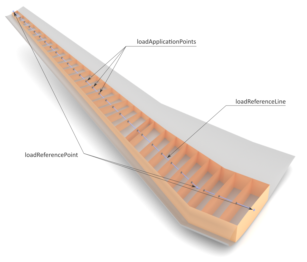
| loadApplicationPoints | [0, 1] | List of points at which load vectors are applied to |
| loadReferenceLine | [0, 1] | Reference axis (line) for load distribution |
| Name | Type | Required | Description |
|---|---|---|---|
 externalDataDirectory externalDataDirectory |  string string | ||
| externalDataNodePath | string | ||
| externalFileName | string | ||
| uID | ID | Yes |
A point set contains discrete spatial points at which loads are applied (e.g., aerodynamic or structural loads). A typical procedure in CPACS is as follows:
- Reference a wing, fuselage or control surface by its uID using the componentUID node.
- Define a reference axis through the above component with the loadReferenceLine element to specify where a load distribution shall be applied.
- Compute the intersections with (e.g.) ribs of the referenced component (wing, fuselage or control surface) and write the results into loadApplicationPoints. This procedure results from common practice where the forces in structural analyses are typically introduced at structural elements such as ribs and spars. With respect to preliminary aircraft design a two-dimensional load distribution is preferred. However, an arbitrary distribution of the load application points is possible (without the intersection of structural elements with a reference axis in the previous step), for example to define discrete load distributions on the wing surface in streamwise and spanwise direction.
- Specify the location and orientation of cut loads in the cutLoadIntegrationPoints element and the corresponding connectivity information in the connectivities node.