| cpacs Element |
CPACS root element
Namespace: Empty
Schema: Empty

| Name | Occurrences | Description |
|---|---|---|
 All All | ||
 airlines airlines | [0, 1] | airlinesType |
| airports | [0, 1] | airportsType |
| flights | [0, 1] | flightsType |
| header | headerType | |
| missionDefinitions | [0, 1] | missionDefinitionsType |
| studies | [0, 1] | Design study parameters and results. |
| toolspecific | [0, 1] | toolspecificType |
| vehicles | [0, 1] | vehiclesType |
- Version
V3.1
- Date
2019-08-27
1. Overview
The Common Parametric Aircraft Configuration Scheme (CPACS) is an XML-based data format for describing aircraft configurations and their corresponding data.
This XML-Schema document provides a description of the CPACS data structure that can be used for automatic validation as well as for documentation purposes. In this Schema, type declarations and element definitions are seperated. This means, there is e.g. a pointType class, containing x, y and z components. This class is then used in different places under different names (e.g. the "translation" node in "transformation" is made of pointType, meaning it has x, y and z subnodes.)CPACS is an open source project published by the German Aerospace Center (DLR e.V.). For further information please go to http://software.dlr.de/p/cpacs/home/
You can display the text based version of CPACS in every text editor. Further tools are for example www.eclipse.org
2. Coordinate Systems
Coordinate systems are a regular cause for ambiguous interpretation of data. In CPACS, the reference coordinate system is the CPACS-coordinate system. This coordinate system is used for most of the data. A single exception is made in order to keep aerodynamic data in an aerodynamic coordinate system. The following paragraphs outline the determination to known coordinate systems.
The CPACS coordinate system is the coordinate system identified by TIGL, CPACS's geometric library. It is a right-handed coordinate system. If an aircraft is defined in the CPACS coordinate system it will usually follow the directions listed in the table below.
Therefore, the CPACS coordinate system can be confused with the body-fixed coordinate system. While often the CPACS coordinate system and the body-fixed coordinate system overlap, this must not always be true. Several definitions for body-fixed coordinate systems exist (x-axis through nose and tail, x-axis perpendicular to nose plane). For non-symmetric aircraft, body-fixed coordinate systems become even more complicated. Hence, analysis tools should stick to the CPACS-Coordinate system. It remains to the designer to model the geometry accordingly.
The CPACS coordinate system does not rotate with flow. Hence, aerodynamic calculations do rotate their flow relative to the CPACS-coordinate system. If not stated explicitly different, e.g. for target lift-coefficients, results are returned in the CPACS coordinate system, i.e. the cfx-coefficient is parrallel to the CPACS x-Coordinate, regardless of the way the geometry is defined.
The following table gives an "best-practice" advice on how to locate a geometry within CPACS. Different approaches are, of course, valid as well.
| Axis | Direction | Description |
| x | tailwards | from nose to tail |
| y | spanwise | from symmetry plane to the right wingtip |
| z | upwards | from landing gear to tip of vertical tailplane |
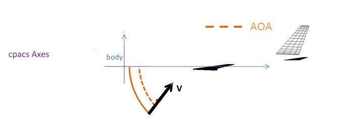
The following pictures give an example for a geometry that is defined in alignment with the CPACS coordinate system, i.e. the body coordinate system overlaps with the CPACS coordinate system.
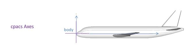
The aerodynamic analysis is relative to the CPACS coordinate system. That is, the angle of attack is represented by the dashed orange line. Results of the aerodynamic calculation are given in the CPACS coordinate system.
The following pictures give an example for a geometry that is not defined in alignment with the CPACS coordinate system. It is a valid CPACS file, but chosen here for demonstrative purposes.
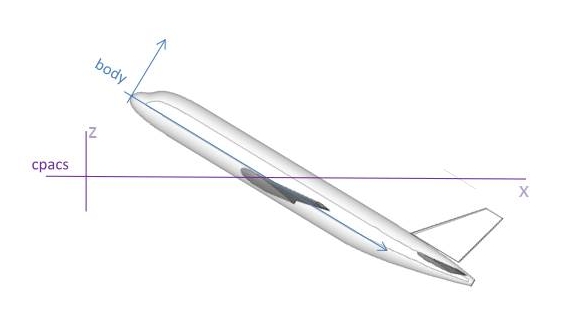
The body axes and the CPACS coordinate system do not align. That is, the origin of the geometry is not at CPACS (0,0,0) but at a point in positive x- and z-direction.
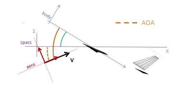
Again, the aerodynamic analysis is relative to the CPACS coordinate system. That is, the angle of attack is represented by the dashed orange line. Results of the aerodynamic calculation are given in the CPACS coordinate system.
3. Units
There are no explicit attributes describing units in CPACS. The general convention is that all values must be given in the following SI-units:
| [m] | Position, Distance |
| [m^2] | Area |
| [m^3] | Volume |
| [kg] | Mass |
| [s] | Time |
| [K] | Temperature |
or in derived units, e.g.:
| [N] | Force |
| [Nm] | Moment |
| [W] | Power |
| [J] | Energy |
The only non SI unit used throughout CPACS is the angle in degrees [°]. For the sake of an intuitive use the angles are given in degrees rather than in radian [rad].
| [°] | Angle |
4. Splitting up a CPACS dataset into several files
To provide a better overview, it is possible to split up a CPACS dataset into several files. This can be done by inserting an <externaldata> node at an arbitrary position into the datatset. This node contains a <path> node with a URI to the external file(s), followed by one or more <filename> nodes, containing each a name of a file to be included at that position. Below, an example of such external data is given:
<?xml version="1.0" encoding="utf-8"?>
<cpacs xsi:noNamespaceSchemaLocation="cpacs_schema.xsd" xmlns:xsi="http://www.w3.org/2001/XMLSchema-instance">
    <vehicles>
        <profiles>
            <wingAirfoils>
                <externaldata>
                    <path>file:://airfoils</path>
                    <filename>NACA0010.xml</filename>
                    <filename>NACA2412.xml</filename>
                </externaldata>
                <airfoil uID="NACA0012">
                    <name>NACA 0012 Airfoil</name>
                    <pointList>...</pointList>
                </airfoil>
            </wingAirfoils>
        </profiles>
    </vehicles>
<cpacs>
Such an external file would look like:
<?xml version="1.0" encoding="utf-8"?>
<airfoil uID="NACA0010">
    <name>NACA 0010 Airfoil</name>
    <pointList>...</pointList>
</airfoil>
The file would be included completely, except for its title line <?xml version="1.0" encoding="utf-8"?> . This concept can also be used recursively (external files of external files), then it is important to prevent circle connections (file "A" loading file "B" loading file "C" loading again file "A" ...).
For path URI adresses, the trailing file separator "/" may be omitted. Below, some examples for path URIs are given:
- Absolute local path: "file:///tmp" or "file:///c:/windows/tmp"
- Relative local direcotry: "file://relativeDirectory" or "file://../anotherRelativeDirectory"
- Remote net ressource: "http://www.someurl.de"
A CPACS dataset with external files, being loaded by a special library like the TIVA XML Interface TIXI, shall collect all its external datafiles and build up a single tree from them. A validation against this schema is only possible for such a single tree file; the <externaldata>nodes are not recognized by it. To preserve the information, necessary to split the file up into external files again later, externaldata information is maintained within three attributes of the former external top node:
- externalFileName - Name of the file where the external data shall be saved
- externalDataDirectory - Directory of the external data file. Its content is analogous to the <externaldata>'s <path>node described above.
- externalDataNodePath - XPATH of the node which is replaced with the content of the external file. In case that it is an external file of an external file, then it is the XPATH in the outer external file. If, e.g., in the example above the <pointList>node would have also been loaded from an external file, then the entry would just be: externalDataNodePath="/airfoil". This is used primarily for loop-detection.
The single tree for the example above would look like:
<?xml version="1.0" encoding="utf-8"?> <cpacs xsi:noNamespaceSchemaLocation="cpacs_schema.xsd" xmlns:xsi="http://www.w3.org/2001/XMLSchema-instance"> <vehicles> <profiles> <wingAirfoils> <airfoil uID="NACA0010" externalFileName="NACA0010.xml" externalDataDirectory="file://airfoils" externalDataNodePath="/cpacs/vehicles/profiles/wingAirfoils"> <name>NACA 0010 Airfoil</name> <pointList">...</pointList"> </airfoil> ... <airfoil uID="NACA0012"> <name>NACA 0012 Airfoil</name> <pointList>...</pointList> </airfoil> </wingAirfoils> </profiles> </vehicles> <cpacs>
5. UIDs and references
The CPACS-dataset often uses references between nodes. Typically, these references define connections between parts that are located somewhere else in the dataset (e.g. a wing is connected to a fuselage, a specific engine from the "engines"-section is used, ...). These connections are made, using UID attributes. This means, that a node, that shall be referenced (e.g. an engine type, an airfoil geometry, a mission definition, ...), gets an additional UID attribute, consisting of a unique (in the scope of the whole CPACS dataset) text, like:
<fuselage uID="ATTAS fuselage">...
Such a node with a UID is then typically referred to by a subnode, like:
<wing>
    <name>ATTAS main wing</name>
    <parentUID isLink="True">ATTAS fuselage</parentUID>
    ...
It is absolutely essential to ensure that a UID attribute is unique within the whole dataset, as searching for this name is the only way to resolve the reference!
This is also important for testing. All nodes that refer to an UID like e.g. parentUID carry an additional attribute "isLink". If this attribute is true the dataset can be tested for valid UIDs.
UID can either be named according to their appearance in the hierarchy e.g. uid=""mainWingKinkSection" or by automatically placing identifiers e.g. via processor runtime dates
6. Symmetry
Sometimes it might be useful to specify a part of the aircraft as symmetric instead of holding all the data twice in nearly identical form in the dataset (e.g. left and right wing are usually identical, except for the sign of the y-coordinate). Hence, some parts offer the option to set a symmetry attribute for them, like:
<wing symmetry="x-z-plane">...
This attribute explains that the whole part with all its subnodes is symmetric to the given plane. Possible planes are:
- x-y-plane
- x-z-plane
- y-z-plane
UIDs, references and symmetry
All nodes, e.g. parentUID, in CPACS that refer to a component that holds symmetry attribute, e.g. wing, have to carry the symmetry attribute as well.
The symmetry attribute may take three values: symm, def, full:
- def: The element refers to the geometric component that has a symmetry attribute and refers only to the defined side of the geometric component.
- symm: The element refers to the geometric component that has a symmetry attribute and refers only to the symmetric side of the geometric component. (Similar to the previous _symm solution)
- full: The element refers to the geometric component that has a symmetry attribute and refers to the complete component. (This is the default behaviour)
<wing uID="ATTAS main wing" symmetry="x-z-plane">
    ...
    <segments>
        <segment uID="ATTAS main wing innersegment">
        ...
In the example above, to refer to the "other" side of the wing on must use the definition as such:
<loadcase>
    ...
    <segments>
        <segment>
            <segmentUID isLink="True" symmetry="symm">ATTAS main wing inner segment</segmentUID>
            <strip>...
7. Vectors and arrays
For large data sets (e.g. increments of aerodynamic coefficients due to control surface deflections) it is advantageous to map them via vectors and arrays instead of using single nodes for each data value. The following definition of vectors and arrays, indicated by the mapType attribute, is therefore introduced in CPACS:
- mapType="vector"
The vector is meant as a one-dimensional-array. In such a node, the values are given in a semicolon separated list:
<angleOfAttack mapType="vector">0.;1.5;3.;4.5;6;7.5;9.</angleOfAttack>
- mapType="array"
The array is meant for multi-dimensional-arrays. Again, the values are contained in a semicolon separated list. An array is always preceded by a sequence of vectors, containing the dimensions and index values of it:
<altitude mapType="vector">1000.; 2000.; 3000.</altitude>
    <incrementMaps>
        <incrementMap uID="incMap_b3ac2">
            <controlSurfaceUID>InnerWingFlap</controlSurfaceUID>
            <controlParameters mapType="vector">-1;-0.5;0;1</controlParameters>
                <dcl mapType="array">11.; 12.; 13.; 14.; 15.; 21.; 22.; 23.; 24.; 25.; 31.; 32.; 33.; 34.; 35.</dcl>
Values for cl increments:Control parameter = -1 Control parameter = -0.5 Control parameter = 0 Control parameter = 1 Altitude = 1000m 11. 12. 13. 14. Altitude = 2000m 21. 22. 23. 24. Altitude = 3000m 31. 32. 33. 34.
8. Control Parameters
Control parameters are abstract parameters, linking a generic floating point value to a certain status of a control device (e.g. control surface, landing gear, suction system, brake parachute, ...). For control surfaces, such a data pair (control parameter and control surface deflection status) is called a <step> and the ordered list of all steps for a control surface forms its deflection <path>.
The control parameter values for each step are arbitrary floating point values. However, it is strongly recommended to use values between -1. and +1., or between 0. And +1. (depending on the type of control surface). The smallest and the largest value implicitly define the maximum deflection limits. It is mandatory, that the value “0.” is within the specified range, as this value is treated as undeflected and used to specify a “clean” aircraft configuration (e.g. used in the clean aero performance map). It is recommended, but not mandatory to specify a <step> with a <controlParameter> of 0. Consequently, no <controlParameter> must be used twice within a single <path> definition. Deflection values between two specified steps are handled by linear interpolation.
The following example shows the usage of control parameters within a control surface deflection path definition:
<controlSurfaces>
  <trailingEdgeDevices>
    <trailingEdgeDevice uID="InnerWingFlap">
      ...
      <path>
        ...
        <steps>
          <step>
            <controlParameter>-1</controlParameter>
            <hingeLineRotation>-20.</hingeLineRotation>
          </step>
          <step>
            <controlParameter>-0.5</controlParameter>
            <hingeLineRotation>-10.</hingeLineRotation>
          </step>
          <step>
            <controlParameter>0</controlParameter>
            <hingeLineRotation>0.</hingeLineRotation>
          </step>
          <step>
            <controlParameter>1</controlParameter>
            <hingeLineRotation>5.</hingeLineRotation>
          </step>
        </steps>
        ...
9. Atmosphere
At some places in CPACS, an atmosphere has to be selected (e.g. for connecting an altitude with a certain pressure or density). Currently, CPACS does only support a single atmospheric model: The ICAO Standard Atmosphere (ISA) from 1993 (see ICAO Doc 7488/3 'MANUAL OF THE ICAO STANDARD ATMOSPHERE', third edition, 1993) It covers temperature, pressure, density, speed of sound, dynamic viscosity and kinematic viscosity with respect to altitude. In CPACS, 'altitude' means what is called 'geopotential altitude' (H) in the ISA reference document and is given in [m]. For details, see ISA manual, section 2.3, page E-viii f. ISA covers a range from -5000 m to 80000 m.
Temperature offsets are introduced on top of the definitions in the ISA manual (which does not cover such variations). The offset model is based upon the idea that the pressure at a fixed geopotential altitude is independent from temperature offset (pressure altitude). The temperature offset changes only the density (following rho = p / Gas Constant / T) (and viscosity, of course)
CPACS 3.1
Release in August 2019
- Redefinition of aeroPerformanceMaps
- Added nodes for detailed engine pylons and nacelles
- Added nodes to model generic walls
- Extension of material definition
- Added fuselage compartment definition
- Added fuselage fuel tank definition
- Explicit wing stringer definition integrated into wing stringer definition
- RelativeDeflections renamed to control parameters
- Control distributors modified to only have a single command input vector
- "cpacsVersion" restricted to current schema version
- Code cleanup
- Cpacs_schema.xml removed
- Documentation adaptions
CPACS 3.0
Release in Jul 2018
- New component segment definition; this is affecting all structural components of wings
- Renamed angleOfYaw into angleOfSideslip
- Fixes in documentation
- Made all uID attributes required
- Minor fixes in choices and typos
- Added nodes for the geometry of generic system components
- Added performance requirements for aircraft models
- Redefined the whole mission definition including point performances
- Made link to missionUID in trajectory optional
- Added new parameters to enginePerformanceMap
- Relocated mFixedLeadingEdge and mFixedTrailingEdge within the massBReakdown structure
- Changed aeroPerformanceMap to use altitude and standard atmosphere instead of reynolds number
- Added an optional local direction for guide curves and an illustration image
- Announced toolspecifics definitions as deprecated; will be removed from CPACS in next release and should be managed in separate namespace by tool maintainers
- Added an option for aerodynamic performance maps of elastic aircraft
- Enabled the definition of multiple aeroPerformanceMaps
- Enabled the use of spar points for rib placement and rib points for spar placement
- Added explicit stringer definitions for wing cells
- All issues for this release can be found online
- https://github.com/DLR-LY/CPACS/issues
CPACS 2.3.1
Release in Jul 2016
- CPACS 2.3.1 is a beta release, all parameters may be subject to change.
- Added a branch for the definition of design studies.
- Added thermal properties for materials.
- Revised the definition of flights/flightplans.
- Added an airline definition.
- Added structure for skid gear components.
- Changed the units for material density to SI units.
- Revised the top level fleets node and put it into the new airline node.
- All issues for this release can be found online
- https://github.com/DLR-LY/CPACS/issues
CPACS 2.3
Release in Nov 2015
CPACS 2.3 is the fourth public release of CPACS. Major changes include:
- Included vector notation for weight and balance.
- Included flight system and flight dynamic information.
- Included top level aircraft requirements.
- Included a prototype for detailed nacelle geometries.
- Included structural mounts.
- Extended aero data set for loads.
- Extended the mass breakdown.
- Updated the symmetry definition, please take a look at the documentation point 5 and 6.
- All issues for this release can be found online
- https://github.com/DLR-LY/CPACS/issues
CPACS 2.2.1
Release in Feb 2015
- CPACS 2.2.1 is a beta release, all parameters may be subject to change.
- Included preliminary definition of guidecurves.
- Included additional means to describe the wing structure.
- Included preliminary fuselage fuel tanks.
- Included preliminary load envelope.
- Included preliminary flight performance and flight qualities. (flight dynamics will follow)
- Updated toolspecifics
- Updated uncertainty definition
- all issues can be found online
- http://code.google.com/p/cpacs/issues/list
CPACS 2.2
Release in May 2014
- CPACS 2.2 is the third public release of CPACS. Major changes include
- Additions and changes to the loadCaseType.
- Included additional genericGeometricEntities for bellyfairings etc.
- The mass breakdown is extended for a more detailed fuselage strucuture.
- Steadiness information on the geometry is excluded from CPACS 2.2. CPACS 2.3 will include optional guidelines for smoother surfaces.
- Uncertainties can now be specified (CPACS 2.2alpha doubleBaseType, CPACS 2.2 also in vector notations)
- all issues can be found online
- http://code.google.com/p/cpacs/issues/list
CPACS 2.1
Release in May 2013
- CPACS 2.1 is the second public release of CPACS. Most of the implementation was already included in CPACS 2.01
- included fuselage structure and cabin definition
- all data is defined according to the CPACS coordinate system. That is the initial coordinate system in which geometries are defined. Therefore, it can but must not meet your body axis.
- the mass breakdown is extended for a more detailed wing strucuture
- profiles can now be included based on a two-dimensional class shape transformation. The old parametrization will still be available. TIGL will learn CST asap.
- all issues can be found online
- http://code.google.com/p/cpacs/issues/list
CPACS 2.01
Release in Nov 2012
- CPACS 2.01 is an internal release for the VAMP project. It is the testbed for CPACS 2.1
- included fuselage structure
- additions to the load case definition
- all issues can be found online
- http://code.google.com/p/cpacs/issues/list
CPACS 2.0
Release in Mar 2012
- CPACS 2.0 is the first public release
- large impacts on the documentation
- all issues can be found online
- http://code.google.com/p/cpacs/issues/list
- compatible with TIGL 2.0
- excluded fuselage structure, reintegration in CPACS 2.1
CPACS 1.6
Release in Jul 2011
- Thanks for the input on the documentation to Felix Dorbath, Till Pfeiffer, Alexander Koch, Falk Heinecke and Tom Otten
- preliminary added enginePylons
- deleted seatAssemblyPositionType
- updated toolspecific blocks from handbook aero and cpacs mass updater
- added weight and balance definition
- added loads reference axis and dynamic aircraft model
- added wing documentation
- added weights documentation
- added fleet documentation
- added paramam toolspecific documentation
- added wing tank definition
- changed some names in the massBreakdown
- deleted old loadCaseDefinitions
- no more plural element for loadAnalyses
- shifted groundforces to groundloadcases, this will need an update
- added noseLandingGear
- mainLandingGear can now have plural SideStruts
CPACS 1.5
Release in Feb 2011
- uID for transformation
- extended stringUIDBaseType with optional attribute isLink
- all elements xxxUID are now of Type stringUIDBaseType
- added new material definition from FA to distinguish between diffent material types
- changed fuselage structure definition due to input from BK
- changed rib definition in cells in component segments
- cleaned up material definition in component segments
- added cpacsVersion information to the header and updates types
- added area and length to the loadCase reference on wing strips
- added wingFuselageAttachment
CPACS 1.4
Release in Nov 2010
- Geometry definition for engine and nacelle added
- Trailing Edge Devices, Leading Edge Devices and Spoilers added
- Rotorcraft added, similar to aircraft
- Splitted up multiple Point Types
- sparCell added uID
- new inline Documentation introduced in CPACS type
CPACS 1.3
Release in Aug 2010
- Fuel definition added
- Introduced component segments for the wing structure
- Mission definition was updated
- VSAero toolspecific data updated
CPACS 1.2
Release in May 2010
- Fuselage Structure Elements are updated following the input from BK
- stringers>arbitrary additional parameters: yBezugAtStartX, zBezugAtStartX, yBezugAtEndX, zBezugAtEndX
- paxCrossBeams additional parameters: startX, endX
- cargoCrossBeams additional parameters: startX, endX
- paxCrossBeamStruts additional parameters: startX, endX
- cargoCrossBeamStruts additional parameters: startX, endX
- structure>pressureBulkhead: positionX instead of positionZ
- reinforcementNumberVertical: number of vertical reinforcements
- reinforcementNumberHorizontal: number of horizontal reinforcements
- maxFlectionDepth: max camber of pressure bulkhead
- reinforcementNumber: number of reinforcements rear pressure bulkhead
- sheetProperties: definition of sheet properties
- innerRadius: inner radius of the pressure bulkhead
- Dummy Wingbox element is included. This definition needs further enhancements
- cpacs>vehicles>aircraft>model>fuselage>fuselage>structure
- Wingbox:
- xStart: start of the wingbox area
- xEnd: end of the wingbox area
- zStart: upper limit of the wingbox area
- Damping Derivaties are added in the form of dcfxdp, dcfxdq, dcfxdr, dcfydp, etc. The data will be stored in the model/global/aeroperformaneMap under a new dampingDerivatives element. Unit is deg/sec.
- StructureProfiles are defined in the profiles element. They are referenced in structuralElements for several entities such as stringer, frame etc. Currently they are referenced via 'structuralProfileUID' for name consistency it should be either only 'structure' or only 'structural'
- Control Commmands. The chain between pilot inputs and controlsurface deflections is now closed.
- Parameters located at cpacs\vehicles\aircraft\model\systems
- cockpitControl: links from pilotInput to commandCase
- commandCase: links from commandCase to controlDistributor or controlFunction
- controlDistributor links to the controlSurface
- controlLaws includes controlModes automatic and manual
- controlModes contain controlFunctions
- TraFuMo toolspecific data added
CPACS 1.1
Release in Feb 2010
- Fleets model added. The fleets modeling from CATS is introduced to CPACS 1.1
- Reference changed. The reference type in wingSegmentStripCoefficientsType was changed from referenceType to pointType