| path Element |
Definition of the deflection path of the control surface.
Namespace: Empty
Schema: Empty

| Name | Occurrences | Description |
|---|---|---|
 Sequence Sequence | ||
 innerHingePoint innerHingePoint | controlSurfaceHingePointType | |
| outerHingePoint | controlSurfaceHingePointType | |
| steps | Definition of the steps of the control surface deflection path. |
| Name | Type | Required | Description |
|---|---|---|---|
 externalDataDirectory externalDataDirectory |  string string | ||
| externalDataNodePath | string | ||
| externalFileName | string |
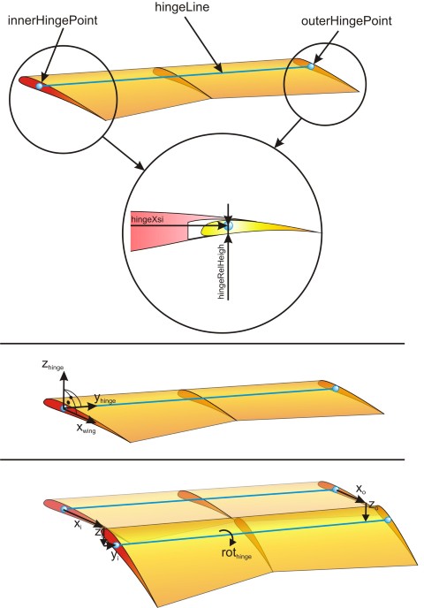
The deflection path of a control surface is described with respect to two hinge points - one at the inner border of the control surface and one at the outer border of the control surface. Those two points are defined using the xsi and relative hight coordinates of the parent. Therefore those points can also lay outbound of the control surface. Those two points defined the hinge line, which is a straight line between the two points.
The deflection path of the control surface is defined within the hinge line coordinat system. This is defined as follows: The x-hinge coordinate equals the wing x-axis. The y-hinge coordinate equals the hinge line axis (see above; positive from inner to outer hinge point). The z-hinge line is perpendicular on the x-hinge and y-hinge coordinate according to the right hand rule. The rotation of the control surface is defined as rotation around the positive y-hinge line.
The deflection of the is defined in any number of steps. The deflection of the control surface is done as follows: First the x-deflection at the inner and outer border; afterwards the z-deflection of the inner and outer border; last the y-deflection of the inner border. The y-deflection is only defined at the inner border, as it is identical to the outer border. If no values for the outer border deflection are given, they default to the values of the inner border.
An example can be found below: