| componentSegment Element |
ComponentSegment of the wing.
Namespace: Empty
Schema: Empty

| Name | Occurrences | Description |
|---|---|---|
 Sequence Sequence | ||
 name name | ||
| description | [0, 1] | Description of the componentSegment. |
| fromElementUID | Reference to the element from which the componentSegment shall start. | |
| toElementUID | Reference to the element from which the componentSegment shall end. | |
| structure | [0, 1] | Structure of the wing |
| controlSurfaces | [0, 1] | controlSurfacesType |
| path | [0, 1] | Description of deflection path of componentSegments (e.g. used for trimmable HTPs). |
| wingFuselageAttachments | [0, 1] | Definition of the wing-fuselage attachment. |
| wingWingAttachments | [0, 1] | List of wingWingAttachments. |
| wingFuelTanks | [0, 1] | List of wing fuel tanks. |
| wingStructuralMounts | [0, 1] | wingStructuralMountsType |
| Name | Type | Required | Description |
|---|---|---|---|
 externalDataDirectory externalDataDirectory |  string string | ||
| externalDataNodePath | string | ||
| externalFileName | string | ||
| uID | string |
Within componentSegments the wing structure, the control surfaces, the wing fuel tanks and the wingFuselageAttachment is defined by using relative coordinates.
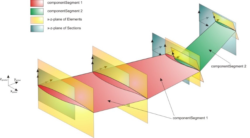
A componentSegment is defined in the same way as segments: from one cross section (sections->elements) to another. Compared to segments one componentSegment can can start and end at elements that are not consecutive. Therefore that one componentSegment can be the combination of several segments. Each wing has at least one componentSegment (from root to tip). The maximal number of componentSegments equals the number of segments (each segment is defined as one componentSegment).
In principal a componentSegment can combine any number of segments. But if in one section two elements are defined, the componentSegment has to start/end there as no well-defined relative coordinats can be defined if steps in the wing occure.
An example for wing componentSegments can be found in the picture below:
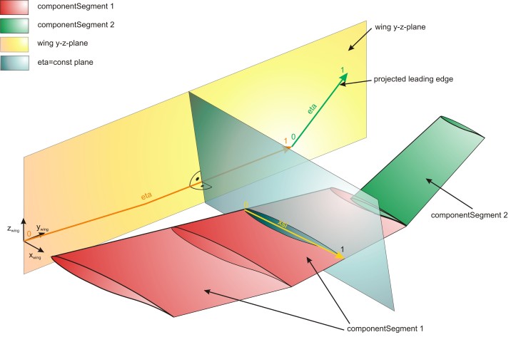
Within componentSegments a relative spanwise coordinate (eta) and a relative chordwise coordinate (xsi) is defined. Those coordinates are used for the definition of e.g. wing structures and control surfaces. The eta coordinate is defined by the line that occures due to the projection of the wing leading edge on the wing y-z-plane. The beginning of this line at from-element equals eta = 0, while the end of this line at the to-element equals eta = 1. All wing positions that lay in a plane, whose normal axis the eta-line is, have the same eta coordinate. The crossing points of the wing leading and trailing edge with this planes define the xsi coordinate from 0 (leading edge) to 1 (trailing edge). A relative height coordinate is defined by the right hand rule at each eta-xsi-position. The relative hight equals 0 at the lower skin and 1 at the upper skin. Pleas not that the orientation of the relative hight vector therefore changes if the order of the 'from' and 'to' lement are changed.
An example for the definition of the relative axes can be found in the picture below:
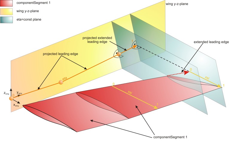
If e.g. the 'to'-element is not heading in flight direction (see picture below) and the leading edge of the wing ends more inbound than the trailing edge, the wing extended virtually to the maximal eta position (trailing edge). The eta-coordinate is defined in this case by the projection of the real leading edge and by the virtual projection. In this case the xsi-coordinate at the tip is defined by the extended leading edge and the trailing edge. At a negative rotaion of the 'to'-element would lead to an virtual extension of the rear part of the wing. Skew 'from'-elements are handeld similar.
An example for the definition of the relative axes at a skew tip can be found in the picture below: